TM-9-1240-401-34-P - Page 224 of 590
TM 9-1240-401-34&P
5-26. M117/M117A2 PANORAMIC TELESCOPE FINAL INSPECTION AND ADJUSTMENT
- continued
I
a. SETTlNG UP AZIMUTH TESTING FIXTURE - continued
I
21
22
23
24
25
26
27
28
29
30
31
32
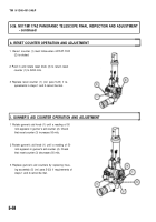
Install reflecting mirror assembly (14) on alinement
gage assembly (13).
Remove lamp assembly (17) and diffusion disk
from collimating projector (11).
Replace lamp assembly (17) with partial reflector at
approximately a 45° angle.
Sight through collimating projector (11) and adjust
collimating projector (11) and fixture adapter (7)
until image of test reticle, as reflected by reflecting
mirror assembly (14), is superimposed on test
reticle. Adjust collimating projector (11) in elevation
and fixture adapter (7) in defelction.
Clamp fixture adapter (7) in place with three cam-
Iock screws (18).
Remove alinement gage assembly (13) from fixture
adapter (7).
Set collimating projector (11) to 88 yards (80 me-
ters).
Install diffusion disk on collimating projector (11).
Install lamp assembly (17) on collimating projector
(11).
Install M117/M117A2 panoramic telescope (19) on
fixture adapter (7) and secure with two latches
(20).
NOTE
Ensure that dioptometer (21) is adjusted to
present a sharp, clear image of the diop-
tometer reticle.
Install dioptometer (21) in dioptometer holder (22)
on surface gage (23).
Adjust height of dioptometer (21) to height of tele-
scope eyepiece (24).
5-50
Back to Top


