TM-9-1240-401-34-P - Page 231 of 590
5-57
TM 9-1240-401-34&P
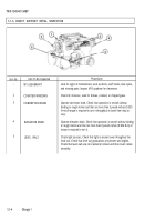
j. LEVEL TRAVEL AND LIFT
1
2
3
4
5
6
7
8
9
10
11
Set azimuth fixture ring (1) to "0" coincidence on
azimuth testing fixture (2).
While sighting through M117/M117/A2 panoramic
telescope eyepiece (3), rotate azimuth knob (4)
and elevation knob (5), until M117/M117A2 pano-
ramic telescope reticle coincides with reticle of
collimating projector (6).
Rotate azimuth fixture ring (1) 800 roils counter-
clockwise
Rotate azimuth knob (4) clockwise until retitles
coincide.
Check that line of sight does not deviate from hori-
zontal by more than 6.0 mil.
Rotate azimuth knob (4) clockwise approximately
one-half revolution while observing reticle.
Rotate azimuth knob (4) slowly counterclockwise
until retitles coincide.
Check that line of sight changes no more than 0.5
mil from reading in step 5.
Repeat steps 3 thru 8 until azimuth fixture ring (1)
has made two full revolutions.
During level travel test, direction of cap rotation
shall be reversed. Any vertical displacement of line
of sight with respect to horizontal target line result-
ing from this reversing of travel shall not exceed
2.0 mil. This test shall be performed at minimum of
eight 800-mil azimuth settings.
If level travel exceeds tolerance specified, check
mounting surfaces of M117/M117A2 panoramic
telescope (7) and fixture adapter (8) for dirt and
burrs. If none of above conditions exist, return
M117/M117A2 panoramic telescope to depot main-
tenance.
Back to Top


