TM-9-1240-401-34-P - Page 228 of 590
5-54
TM 9-1240-401-34&P
5-26. M117/M117A2 PANORAMIC TELESCOPE FINAL INSPECTION AND ADJUSTMENT
- continued
I
g. PARALLELISM OF RETICLE AND IMAGE
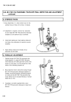
1 Rotate azimuth knob (1) until reticle line of
M117/M117A2 panoramic telescope (2) coincides
with reticle line of collimating projector (3).
2 Check image tilt through two full revolutions of the
cap assembly. The image of a vertical target line
shall be vertical within 0.62 mils or 2° of arc over
the full field of view of the dioptometer (4).
h. PLUMB TRAVEL AND LINE OF SIGHT TRAVEL
1 Collimate M117/M117A2 panoramic telescope (ref.
para 5-26c).
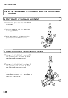
2 Suspend plumb line (1) to one side of azimuth test-
ing fixture (2).
3 Rotate azimuth knob (3) to sight onto plumb line
(1).
4 Install a parallax shield on M117/M117A2 pano-
ramic telescope eyepiece (4).
5 Place a mark on wall behind plumb line (1), inter-
secting reticle line.
Back to Top


