TM-9-1240-401-34-P - Page 223 of 590
TM 9-1240-401-34&P
5-49
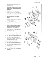
6 Set fixture adapter (7) on adapter support plate (8).
Do not clamp fixture adapter (7) to adapter support
plate (8) at this time.
7 Suspend a plumb line (9) to one side of the azi-
muth testing fixture (1).
8 Install collimator adapter (10) and collimating pro-
jector (11) on tube (12).
9 Install alinement gage assembly (13) on fixture
adapter (7).
10 Remove reflecting mimer assembly (14) from aline-
ment gage assembly (13).
11 Install collimating telescope (15) in alinement gage
assembly (13) and Ioosely claw in place by par-
tially tightening thumbscrew (16).
12 Adjust height of collimating projector (11) so that
line of sight from collimating projector (11) is in
same plane as line of sight from collimating tele-
scope (15).
13 Clamp collimator adapter (10) to tube (12).
14 Rotate fixture adapter (7) until collimating tele-
scope (15) reticle cross line intersection point is in
coincidence with plumb line (9).
15 Revolve collimating telescope (15) until vertical
reticle is in coincidence with plumb line (9).
16 Secure collimating telescope (15) by tightening
thumbscrew (16).
17 Rotate fixture adapter (7) until line of sight from
collimating telescope (15) is in same plane of line
of sight from collimating projector (11).
18 Sight through collimating telescope (15) and re-
volve collimating projector (11) until vertical reticle
line is in coincidence with collimating projector (11)
vertical reticle line.
19 Secure collimating projector (11) by tightening
screws of collimator adapter (10).
20 Remove collimating telescope (15) from alinement
gage assembly (13).
Back to Top


