TM-9-1240-401-34-P - Page 234 of 590
TM 9-1240-401-34&P
5-26. M117/M117A2 PANORAMIC TELESCOPE FINAL INSPECTION AND ADJUSTMENT
- continued
I
o. GUNNER’S AID KNOB TORQUE INSPECTION
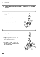
1 Remove headless straight pin (1), gunner’s aid
knob (2), shim(s) (3), and seal (4).
2 Apply grease to inside diameter of seal (4). and
sealing compound to outside diameter of seal (4).
Install seal (4), shim(s) (3), gunner’s aid knob (2),
and headless straight pin (1).
3 Using torque adapter (8213929) (Item 2, appx F)
and torque wrench, check that running torque of
gunner’s aid knob (2) is 1 to 4 pound-inches (0.11
to 0.45 N-m) in both directions.
4 Add or remove shim(s) (3) until required torque is
achieved.
I
p. AZIMUTH KNOB TORQUE INSPECTION
1
2
3
4
5
6
7
Using torque adapter (8599917) (Item 6, appx F)
and torque wrench, check that running torque of
azimuth knob (1) is 4 to 8 pound-inches (0.45 to
0.90 N-m) in both directions.
If requirement in step 1 cannot be met, remove
azimuth knob (1) (ref. para 5-13).
Remove cover (2) (ref. para 5–1 3).
Temporarily install azimuth knob (1), torque
adapter, and torque wrench.
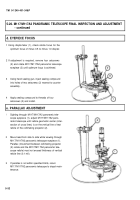
Using adjustable spanner wrench, adjust retainer
(3) until required torque in step 1 is achieved.
Scribe a line on retainer (3) and housing (4). Back
out retainer (3) and apply small amount of sealing
compound and turn in retainer (3) to scribe marks.
Install cover (2) (ref. para 5-17) and azimuth knob
(1) (ref. para 5-13).
q. PURGING AND CHARGING
Refer to TM 750-116 for purging and charging proce-
dures.
5-60
Back to Top


