TM-9-1290-365-24-P - Page 181 of 334
ARMY TM 9-1290-365-24&P
D.4.5.2 CONFIGURATION DESCRIPTION.
a.
The M93 MVS transceiver assembly has three basic configurations. The transceiver assembly,
AY6707292-5, includes an integrated simulation assembly, AY6701 0553, which allows automatic
self test of the microwave section. The transceiver assembly, AY6707292-3, does not include the
integrated simulation assembly. The transceiver assembly, AY6707292-l is an intermediate
version, which includes the integrated simulation assembly and a modified muzzle velocity
processor (MVP) circuit card assembly (CCA) AY6707288-4
b.
Transceiver assembly, AY6707292-5 has a slightly different mechanically structured microstrip
antenna, EA6706148-1, than the other two versions. This is reflected in a different installation of
the RF cable, WA6706563-0.
c.
Transceiver assembly, AY6707292-5, has a slightly different mechanically structured antenna cover,
(AM6701 0650),
than the other two versions.
d.
Transceiver assembly, AY6707292-5, contains a different mechanically structured electro —
magnetic interference (EMI) filter module, AY6707289-3, than the other two versions.
D.4.5.3 INTERCHANGEABILITY.
a. MVP CCA AY6707288-3 can be installed into MVS transceiver assembly AY6707292-3 only. The
integrated simulation assembly is not present.
b. MVP CCA’s, AY6707288-4 and AY67010314 are interchangeable, and can be installed into any
configuration of the MVS transceiver assembly, without affecting fit, form, or function. The MVP
CCA automatically detects the existence of the integrated simulation assembly, and operates
accordingly.
c. Microstrip antenna, EA6706148-1, is interchangeable with microstrip antenna EA6706148-0, and
can be installed into any configuration of the MVS transceiver assembly, without affecting fit,
form, or function.
d. Antenna cover AM67010650 is interchangeable with antenna cover, AM6707834-0 and can be
installed into any configuration of the MVS transceiver assembly, without affecting fit, form, or
function.
e. EMI filter module AY6707289-3 can be installed into antenna cover AM6701 0650 only.
f.
EMI filter module AY6707289-1 can be installed into antenna cover AM6707834-0 only.
g. EMI filter CCA is interchangeable between the two EMI filter modules.
D.4.6 Transceiver Assembly Disassembly.
NOTE
Disassemble transceiver assembly only to the extent necessary to perform the required
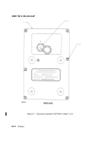
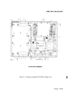
maintenance task. Refer to Figures D-1, D-2 or D-3 in all disassembly procedures.
D.4.6.1 SEPARATION OF BRACKET. If necessary, separate the bracket assembly from the transceiver
assembly in accordance with paragraph 3.5.7 of Chapter 3 in this manual.
Change 1
D-11
Back to Top


