TM-9-1290-365-24-P - Page 287 of 334
ARMY TM 9-1290-365-24&P
switch is modulated by a frequency in the measurement range. The variable attenuator allows adjust-
ment of the reflected signal to a desired level. The phase shifter is used to adjust the reflected signal
phase to the transmitted signal phase. The 40dB fixed attenuator allows operating at the mid-scale of the
variable attenuator, and not at its scale’s edge.
The attenuation of the fixed attenuator is included in the overall insertion loss factor.
The output signal is transferred to the oscilloscope and RMS voltmeter for measurement.
D.9.3 Test Equipment Calibration.
D.9.3.l SME CALIBRATION. The standard measurement equipment is calibrated in accordance with MI
L-STD-45662.
D.9.3.2 MME SPECIAL CALIBRATION.
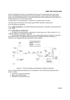
a. The MME for receiver sensitivity is calibrated for overall insertion loss. Refer to Figure D-41. for
schematic description of calibration connection.
b. The calibration data sheets, Table D-26., are to be reproduced locally, as required, for recording
the calibration results. The calibration data sheets must be completed each time a calibration is
performed. The completed calibration data sheets shall be retained.
Figure D-4 1. Microwave Measurement Equipment Calibration Schematic
D.9.3.2.1 Special Calibration Requirements. The calibration of the microwave test equipment is per-
formed in 3 steps:
a. Insertion loss without the PIN switch.
b. Return loss of the PIN switch.
c. Calculation of overall insertion loss.
D-117
Back to Top


