TM-9-2320-209-34-2-3 - Page 150 of 592
TM 9-2320-209-34-2-3
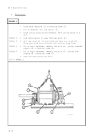
FRAME 27
1.
2.
3.
4.
5.
6.
7.
8.
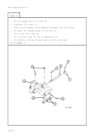
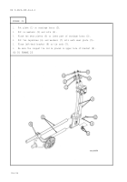
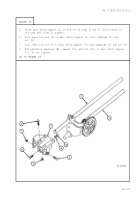
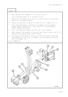
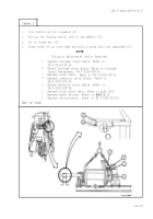
Slide carriage roller assembly (1) on tie rods (2 and 3).
Slide right-hand bracket (4) on tie rods (2 and 3).
Position tie rod support (5) on ends of tie rods (2 and 3). Tie rods must
extend 1/4 inch beyond support.
Tighten two setscrews (6) against tie rods (2 and 3). Tighten nuts (7).
Slide right-hand bracket (4) toward tie rod support (5) until bracket
touches adjusting capscrew (8). There should be 3/4-inch clearance
between bracket and support.
Put on two capscrews, washers, and nuts (9). Do not tighten.
Slide carriage roller assembly (1) back and forth across tie rods (2 and 3) to
make sure that carriage moves without binding.
If carriage binds at either or both ends of tie rods (2 and 3), place shim
stock between tie rods and tie rod support (5), and between tie rods and
main drive support (10).
GO TO FRAME 28
18-139
Back to Top

