TM-9-2320-260-20 - Page 1035 of 1337
TM 9-2320-260-20
13-26. DUMP HOIST CONTROL BOX MAINTENANCE
THIS TASK COVERS:
a. Removal
d. Assembly
b. Disassembly
e. Installation
c. Cleaning and Inspection
INITIAL SETUP
APPLICABLE MODELS
EQUIPMENT CONDITION
M817
Parking brake set (TM 9-2320-260-10).
MATERIALS/PARTS
GENERAL SAFETY INSTRUCTIONS
Two cotter pins
• Eye protection is required when using a wire
Six lockwashers
brush.
Four woodruff keys
• Keep fire extinguisher nearby when using
Gasket
drycleaning solvent.
Rags (Appendix C, Item 22)
Drycleaning solvent (Appendix C, Item 29)
REFERENCES (TM)
TM 9-2320-260-10
TM 9-2320-260-20P
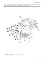
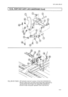
1. Remove two cotter pins (18), straight pins (16), and clevises (17) from levers (2). Discard cotter
pins (18).
2. Remove nut (14), lockwasher (13), and screw (11) from two control box levers (12). Discard lock-
washer (13).
3. Remove two control box levers (12) from control valve trunnion (8) and control box (15).
4. Remove two screws (1), lockwashers (3), nuts (4), and levers (2) from control box (15). Discard
lockwashers (3).
5. Remove four woodruff keys (9) from shafts (10). Discard woodruff keys (9).
6. Remove three screws (6), lockwashers (7), and control box (15) from subframe (5). Discard
lockwashers (7).
13-62
Back to Top

