TM-9-2320-260-20 - Page 1147 of 1337
TM 9-2320-260-20
14-15. COOLANT HEATER PUMP AND MOUNTING BRACKET REPLACEMENT
THIS TASK COVERS:
a. Removal
b. Installation
INITIAL SETUP
APPLICABLE MODELS
REFERENCES (TM)
All
TM 9-2320-260-10
MATERIALS/PARTS
TM 9-2320-260-20P
Five locknuts
EQUIPMENT CONDITION
Three lockwashers
●
Parking brake set (TM 9-2320-260-10).
Cotter pin
●
Battery ground cable disconnected (para. 4-48).
Antiseize tape (Appendix C, Item 30)
1.
2.
3.
4.
5.
6.
7.
8.
9.
10.
11.
12.
NOT E
Close engine oil cooler and heater pump valves prior to removal.
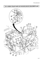
Disconnect fuel line (1) from elbow (2).
Disconnect harness (4) from heater (3).
Remove locknut (20), screw (16), ground leads (17) and (21), and lockwasher (19) from frame (18).
Discard locknut (20) and lockwasher (19).
Remove cotter pin (24) and exhaust tube (23) from heater (3). Discard cotter pin (24).
Remove two safety pins (32), release handles (31), and pull battery box (30) onto running board (29).
NOTE
Have drainage container ready to catch coolant.
Remove clamp (27) and hose (28) from elbow (33).
Remove clamp (6) and hose (5) from adapter (7).
Remove nuts (8) and (26), wire (9), and ground lead (21) from pump (10).
Remove clamp (11) and pump (10) from mount (35).
Remove adapter (7) and elbow (33) from pump (10).
Remove two locknuts (25), screws (12), and bracket (13) from heater mounting bracket (22). Discard
locknuts (25).
Remove two locknuts (15), lockwashers (14), screws (34), and mount (35) from bracket (13). Discard
locknuts (15) and lockwashers (14).
1. Install mount (35) on bracket (13) with two screws (34), new lockwashers (14), and locknuts (15).
2. Install bracket (13), with mount (35), on heater mounting bracket (22) with two screws (12) and new
locknuts (25).
3. Apply antiseize tape to male threads of adapter (7) and elbow (33).
4. Install adapter (7) and elbow (33) on pump (10).
5. Install pump (10) on mount (35) with clamp (11).
6. Install wire (9) and ground lead (21) on pump (10) with nuts (8) and (26).
7. Install hose (5) on adapter (7) with clamp (6).
14-30
Back to Top


