TM-9-2320-260-20 - Page 1209 of 1337
TM 9-2320-260-20
Section IX. TACHOGRAPH KIT MAINTENANCE
14-49. TACHOGRAPH KIT MAINTENANCE
I
THIS TASK COVERS:
a. Tachograph Chart and Lamp Removal
e. Tachograph Installation
b. Tachograph Removal
f. Tachograph Chart and Lamp Installation
c. Instrument Cluster Removal
g. Tachograph Adjustment
d. Instrument Cluster Installation
INITIAL SETUP
APPLICABLE MODELS
All
MATERIALS/PARTS
Tachograph chart
REFERENCES (TM)
TM 9-2320-260-10
TM 9-2320-260-20P
EQUIPMENT CONDITION
• Parking brake set (TM 9-2320-260-10).
• Air reservoirs drained (TM 9-2320-260-10).
• Battery ground cable disconnected (para. 4-48).
GENERAL SAFETY INSTRUCTIONS
• Do not disconnect air lines before draining air
reservoirs.
WARNING
Do not disconnect air lines before draining air reservoirs. Small
parts under pressure may shoot out with high velocity, causing
injury to personnel.
CAUTION
Do not drive vehicle without a tachograph chart installed in
tachograph. Failure to comply may cause damage to tachograph.
a. Tachograph Chart and Lamp Removal
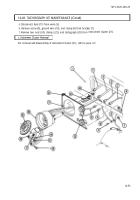
1. Turn key (16) 1/2-turn right and open tachograph (20).
NOTE
Take care not to fold, scratch, or write on tachograph chart when
removing. Chart readings will become illegible if tachograph chart
is damaged.
2. Lift lever (17) and remove tachograph chart (19) from tachograph (20) and tachometer coupling (15).
3. Lift lever(s) (14) and remove lamp(s) (18) horn tachograph (20).
I
b. Tachograph Removal
1. Disconnect oil pressure tube (6) horn oil pressure gage (13).
2. Turn four lock studs (22) 1/4-turn right and separate instrument cluster (21) from instrument
panel (1).
NOTE
Tag all wires and driveshafts for installation.
3. Disconnect speedometer driveshaft (2) and tachometer driveshaft (3) from tachograph (20).
4. Disconnect lead (12) from wire (4).
14-92
Back to Top


