TM-9-2320-260-34-1 - Page 550 of 657
TM 9-2320-260-34-1
9-4. TRANSFER REPAIR (Contd)
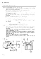
90. Set intermediate shaft (2) end free play using feeler gage.
a.
Install cover (4) on housing (1) with four washers (5) and screws (6). Finger tighten screws (6)
evenly. Cover (4) should be clear of housing (1).
b. Seat both bearings and races by tapping on cover (4) with soft-head hammer.
c.
Evenly tighten screws (6) 20-30 lb-ft (27-41 N
•
m).
d. Using feeler gage, measure gap (11) between cover (4) and housing (1) at three points around
cover (4). Average three readings.
e. Add 0.003 in. (0.08 mm) to reading from step d. above. This is the shim pack (3) thickness to
be installed.
f. Remove four screws (6), washers (5), and cover (4) from housing (1).
NOTE
Perform step g. if plates are not on shaft.
g. Install plate (10) and new locktab washer (8) on rear of intermediate shaft (2) with two
screws (7). Tighten screws (7) 60-80 lb-ft (81-108 N
•
m). Bend tabs (9) of locktab washer (8)
over screws (7).
NOTE
Step 91 uses an adjusting fixture to set output shaft end play.
Step 92 is an alternate method.
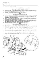
91. Set rear output shaft (12) end free play using adusting fixture.
a.
b.
c.
d.
e.
f.
Position 0.030 in. (0.76 mm) shim pack (13) and adjusting fixture over rear output shaft (12)
and on housing (1) with six washers (15) and screws (14). Tighten screws (14) 40-55 lb-ft
(54-75 N
•
m).
Turning adjusting screw, thread nut (16) onto output shaft (12). Loosen nut (18) as necessary.
Tighten nut (16) 30-40 lb-ft (41-54 N
•
m ).
Tighten front nut (17) 15-20 Ib-ft (20-27 N
•
m) to seat front bearing on rear output shaft (12).
Back off front nut (17) and tighten rear nut (18) 15-20 lb-ft (20-27 N
•
m) to seat rear bearing
on rear output shaft (12).
Back off rear nut (18) and tighten front nut (17) until resistance is felt.
Install dial indicator on adjusting fixture to read end movement of adjusting screw. Zero dial
indicator.
9-50
Back to Top


