TM-9-2320-260-34-1 - Page 90 of 657
TM 9-2320-260-34-1
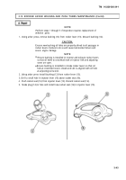
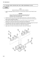
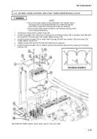
3-15. ROCKER LEVER HOUSING AND PUSH TUBES MAINTENANCE
THIS TASK COVERS:
a. Removal
d. Repair
b. Disassembly
e.
Assembly
c. Cleaning and Inspection
f. Installation
INITIAL SETUP
APPLICABLE MODELS
All
TOOLS
General mechanic’s tool kit
(Appendix B, Item 1)
Torque wrench, 3/8-in. dr.
(Appendix B, Item 4)
Arbor press (Appendix B, Item 7)
Telescoping gage set (Appendix B, Item 74)
Inside micrometer (Appendix B, Item 9)
Outside micrometer (Appendix B, Item 8)
Hex head socket, 3/8-in. dr.
(Appendix B, Item 141)
Radius gage (Appendix E, Figure E-2)
MATERIALS/PARTS
Gasket (Appendix D, Item 91)
Two locknuts (Appendix D, Item 190)
Two performed packings (Appendix D, Item 311)
Lubricating oil (Appendix C, Item 21)
Blue pigment (Appendix C, Item 26)
Sealant (Appendix C, Item 44)
REFERENCES (TM)
TM 9-2320-260-10
TM 9-2320-260-34P-1
EQUIPMENT CONDITION
Parking brake set (TM 9-2320-260-10).
Rocker lever housing covers removed (para. 3-14).
NOTE
All rocker lever housings and push tubes are replaced basically
the same way. This procedure covers the front rocker lever
housing and push tube.
Perform step 1 for No. 1 rocker lever housing.
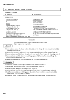
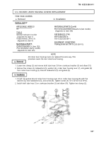
1. Remove two locknuts (2), screws (12), and washers (13) from trunnion bracket (1) and radiator
mount (11). Discard locknuts (2).
2. Remove two screws (4), washers (3), and trunnion bracket (1) from rocker lever housing (8).
3. Loosen six adjusting nuts (16) and turn adjusting screws (15) two turns counterclockwise.
NOTE
Mark rocker lever housing and push tubes for installation.
4. Remove four screws (5), washers (6), lifting bracket (7), rocker lever housing (8), and gasket (9) from
cylinder head (10). Discard gasket (9).
5. Remove six push tubes (14) from cylinder head (10).
3-38
Back to Top

