TM-9-2320-260-34-2 - Page 761 of 863
TM 9-2320-260-34-2
17-22. PERSONNEL HEATER OVERHEAT SWITCH REPLACEMENT
THIS TASK COVERS:
a. Removal
b. Installation
INITIAL SETUP
APPLICABLE MODELS
All
TEST EQUIPMENT
Multimeter (Appendix B, Item 115)
TOOLS
General mechanic’s tool kit
(Appendix B, Item 1)
Tool kit, electrical (Appendix B, Item 106)
MATERIALS/PARTS
Two nut-assembled Iockwashers
(Appendix D, Item 262)
Two screw-assembled Iockwashers
(Appendix D, Item 405)
REFERENCES (TM)
TM 9-2320-260-20
TM 9-2320-260-34P-2
EQUIPMENT CONDITION
Personnel heater removed (TM 9-2320-260-20).
NOTE
●
The overheat switch is removed basically the same for early and
late model heaters. This procedure is for early model heaters.
●
Tag wires for installation.
1. Remove flame detector switch (para. 17-15).
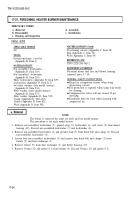
2. Remove nut-assembled lockwashers (1) and shutoff valve lead (2) from overheat switch (8). Discard
nut-assembled lockwashers (1).
3. Remove nut-assembled lockwashers (9), receptacle lead (3), thermostat lead (4), and ignition control
lead (5) from overheat switch (8). Discard nut-assembled lockwasher (9).
4. Remove two screw-assembled lockwashers (7) and overheat switch (8) from heater housing (6).
Discard screw-assembled lockwashers (7).
1.
Install overheat switch (8) on heater housing (6) with two new screw-assembled lockwashers (7).
2. Install ignition control lead (5), thermostat lead (4), and receptacle lead (3) on overheat
switch (8) with new nut-assembled lockwasher (9).
3. Install shutoff valve lead (2) on overheat switch (8) with new nut-assembled lock washer (l).
4. Install flame detector switch (para. 17-15).
17-60
Back to Top


