TM-9-2320-272-10 - Page 384 of 481
TM 9-2320-272-10
3-35
3-11. WHEELS AND TIRES (Contd)
(f)
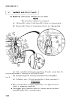
Pull hand chain (5) to slightly raise spare tire (6) from spare tire
carrier base (7). Move spare tire (6) out of bracket area towards back of cab. Pull
spare tire (6) towards side of vehicle until sufficient clearance is obtained to lower
spare tire (6) to ground.
(g)
Pull on hand chain (5) to lower spare tire (6) to ground.
(h)
Remove utility chain (1) securing spare tire (6) to chain fall (4).
(4) Installation
(M929/A1/A2, M930/A1/A2, and M934).
(a)
Place utility chain (1) through rim of spare tire (6) and ring (2) on
utility chain (1). Center ring (2) at top of spare tire (6). Take up slack and hook
utility chain (1) back onto utility chain (1).
(b)
Lower chain fall (4) hook and attach to utility chain ring (2).
(c)
Raise spare tire (6) until it clears tire carrier base (7). Place tire on
tire carrier base (7).
(d)
Lower wheel brace (10), guide threaded bar (8) to notch in spare tire
carrier base (10), and tighten wingnut (9) until snug.
(e)
Remove utility chain (1) from spare tire (6) and chain fall (4) from
support loop (3). Return utility chain (1) and chain fall (4) to tool compartment.
(5) Removal
(M934A1/A2).
NOTE
• This procedure requires two personnel.
• Cable and hook will be attached to spare tire during normal
vehicle operation.
(a)
Push and hold button (14) and remove retaining pin (13) and lift
brace (11) up. Reinstall pin (13) with brace (11) in up position.
(b)
Turn winch handle (12) counterclockwise to remove tension.
Back to Top


