TM-9-2320-272-23-1 - Page 1226 of 1313
FIVE INDICATOR LIGHTS FLASHING - Continued
STEP
12.
IS THE VOLTAGE FROM THE ECU TO THE PRESSURE SWITCH NORMAL?
a.
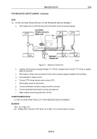
Start engine and run while monitoring the instrument cluster air pressure gauge.
T0424DAA
ELECTRONIC
CONTROL UNIT (ECU)
(INSIDE CAB)
PRESSURE
TRANSDUCER
Figure 12.
Electronic Control Unit .
b.
Operate until air pressure gauge indicates 112-120 psi. If gauge does not reach 112-120 psi or greater,
adjust air governor.
c.
With engine running, drain secondary air tank until air pressure gauge indicates less than 80 psi.
d.
Set multimeter to measure VDC.
e.
Connect CTIS wiring harness cannon plug to ECU.
f.
Place battery switch to ON position.
g.
Connect multimeter red lead to pressure switch connector.
h.
Connect multimeter black lead to a known good ground.
i.
Meter reading should be greater than 18 VDC.
CONDITION/INDICATION
IS THE VOLTAGE FROM THE ECU TO THE PRESSURE SWITCH NORMAL?
DECISION
YES - Go to Step (13).
NO - Replace ECU (Volume 5, WP
0813). Go to Step (17) to verify problem is solved.
TM 9-2320-272-23-1
0146
0146-13
Back to Top


