TM-9-2320-272-23-1 - Page 235 of 1313
HEATING SYSTEM OPERATION
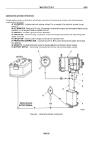
The electrical portion of the heating system is identical for all models covered in this manual and consists of the
following major components and circuitry:
A. PROTECTIVE CONTROL BOX
- Provides 24-volt power to circuit breaker through circuits 5 and 5A and
to heater switch through circuits 27 and 5C.
B. CIRCUIT BREAKER
- Provides overload protection for 24-volt circuits 5, 5A, 27, and 5C leading to the
heater switch.
C. BATTERY SWITCH
- Provides 12-volt battery power from circuit 569 through 569A to the heater.
D. CIRCUIT BREAKER
- Provides overload protection for 12-volt circuit 569A leading to heater switch.
E. HEATER SWITCH
- Controls low and high blower motor speed and has two sources of power: 12-volt
power is supplied through circuit 569A from battery switch and is used to provide low speed; 24-volt power
is supplied through circuit 5C from protective control box and is used to provide high speed.
F. HEATER BLOWER MOWER
- A direct current motor controlled by heater switch through circuit 400.
TM 9-2320-272-23-1
0003
0003-30
Back to Top


