TM-9-2320-272-23-1 - Page 866 of 1313
PROTECTIVE CONTROL BOX ASSEMBLY TEST - Continued
PROTECTIVE
CONTROL BOX
T1066DAA
PROTECTIVE
CONTROL BOX
PROTECTIVE
CONTROL
CONNECTOR
A
B
C
D
E
F
G
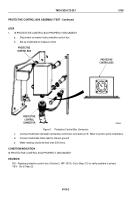
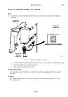
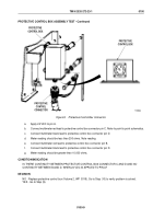
Figure 8.
Protective Control Box Connector.
a.
Apply 24 VDC to pin A.
b.
Connect multimeter red lead to protective control box connector pin C. Refer to point to point schematics.
c.
Connect multimeter black lead to protective control box connector pin D.
d.
Meter reading should be less than 200 ohms. Note reading.
e.
Connect multimeter red lead to protective control box connector pin B.
f.
Connect multimeter black lead to protective control box connector pin D.
g.
Meter reading should be greater than 10,000 ohms.
CONDITION/INDICATION
IS THERE CONTINUITY BETWEEN PROTECTIVE CONTROL BOX CONNECTOR C AND D AND NO
CONTINUITY BETWEEN B AND D, WHEN 24 VDC IS APPLIED TO PIN A?
DECISION
NO - Replace protective control box (Volume 2, WP
0319). Go to Step (10) to verify problem is solved.
YES - Go to Step (9).
TM 9-2320-272-23-1
0100
0100-9
Back to Top

