TM-9-2320-272-23-1 - Page 950 of 1313
ONE OR MORE TRAILER LIGHTS INOPERATIVE - Continued
STEP
2.
IS THERE BATTERY VOLTAGE AT TRAILER RECEPTACLE?
a.
Place battery switch to ON position.
b.
Place truck main light switch in position corresponding to inoperative system on trailer.
c.
Set up multimeter to measure VDC.
T0121DAA
A
L
J
K
N
M
B
C
D
E
F
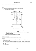
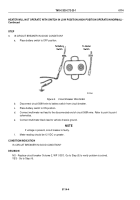
Figure 2.
Trailer Receptacle.
d.
Connect multimeter red lead to the trailer receptacle socket terminal pin that corresponds to circuit being
tested. Refer to point to point schematics.
e.
Connect multimeter black lead to trailer receptacle socket terminal pin L.
NOTE
For stoplight circuit test, air pressure must be maintained at operating pressure and brake
pedal must be depressed.
f.
Meter reading should be greater than 18 VDC for each reading. Note reading.
CONDITION/INDICATION
IS THERE BATTERY VOLTAGE AT TRAILER RECEPTACLE?
DECISION
NO - Go to Step (3).
YES - Go to Step (5).
TM 9-2320-272-23-1
0113
0113-3
Back to Top


