TM-9-2320-272-23-2 - Page 1121 of 1417
ADJUSTMENT
1.
Start engine (TM 9-2320-272-10).
2.
Set engine speed to 1,200 rpm (TM 9-2320-272-10).
3.
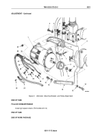
Turn on headlights (TM 9-2320-272-10) to place load on alternator (Figure 5, Item 1).
4.
Using multimeter, check alternator (Figure 5, Item 1) output voltage. Connect black lead to ground cable
(Figure
5,
Item
27) and touch red lead to wire (Figure 5, Item 28). Output voltage should be 27.8 to 28.2 VDC.
If adjustment is required, continue with next step. If no adjustment is required, proceed to Step (8).
5.
Using hex-head driver, remove pipe plug (Figure 5, Item 30) from alternator (Figure 5, Item 1).
6.
Turn adjusting screw counterclockwise to increase or clockwise to decrease voltage.
7.
Apply silicone rubber adhesive to pipe plug (Figure 5, Item 30) threads. Using hex-head driver, install pipe plug
(Figure 5, Item 30) and tighten 24 to 36 lb-in. (3 to 4 N·m).
8.
Turn off headlights (TM 9-2320-272-10).
9.
Stop engine (TM 9-2320-272-10).
10.
Seal wires (Figure 5, Items 25, 26, 27, and 28) and connector (Figure 5, Item 29) completely with silicone
rubber adhesive.
11.
Install terminal cover (Figure 5, Item 23) on alternator (Figure 5, Item 1) with two screw assembly lockwashers
(Figure 5, Item 24).
TM 9-2320-272-23-2
0301
0301-10
Back to Top


