TM-9-2320-272-23-2 - Page 1119 of 1417
ALTERNATOR AND MOUNTING BRACKET INSTALLATION
WARNING
Alternator is heavy. Assistant will help with alternator removal. Failure to comply may result
in injury or death to personnel.
NOTE
Ensure wire connecting points are thoroughly cleaned before connections are made.
1.
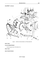
Install alternator link (Figure 4, Item 10) on engine (Figure 4, Item 5) with washer (Figure 4, Item 9) and screw
(Figure 4, Item 8).
2.
Install mounting bracket (Figure 4, Item 6) on engine (Figure 4, Item 5) with four screws (Figure 4, Item 7).
3.
Install alternator (Figure 4, Item 1) on mounting bracket (Figure 4, Item 6) and bracket (Figure 4, Item 4) with
two washers (Figure 4, Item 3) and screws (Figure 4, Item 2). Finger-tighten screws.
4.
Connect wire (Figure 4, Item 26) to connector (Figure 4, Item 27).
5.
Install positive wire (Figure 4, Item 23) on alternator (Figure 4, Item 1) with lockwasher (Figure 4, Item 13) and
nut (Figure 4, Item 14). Tighten nut 45 to 55 lb-in. (5 to 6 N·m).
6.
Install lead wire 566 (Figure 4, Item 24) and capacitor lead (Figure 4, Item 15) on alternator (Figure 4, Item 1)
with lockwasher (Figure 4, Item 16) and nut (Figure 4, Item 17). Tighten nut 20 to 25 lb-in. (2 to 3 N·m).
7.
Install negative wire (Figure 4, Item 25) and capacitor lead (Figure 4, Item 22) on alternator (Figure 4, Item 1)
with lockwasher (Figure 4, Item 18) and screw (Figure 4, Item 19). Tighten screw 82
to
102 lb-in.
(9
to
12
N·m).
8.
Pivot alternator (Figure 4, Item 1) to align with alternator link (Figure 4, Item 10).
9.
Install alternator link (Figure 4, Item 10) on alternator (Figure 4, Item 1) with washer (Figure 4, Item 11) and
screw (Figure 4, Item 12).
10.
Install fan drivebelt (WP
0296).
11.
Connect battery ground cables (WP
0350).
12.
Adjust alternator (Figure 4, Item 1) as found in the ADJUSTMENT section of this work package.
TM 9-2320-272-23-2
0301
0301-8
Back to Top


