TM-9-2320-272-23-2 - Page 1113 of 1417
ALTERNATOR AND MOUNTING BRACKET REMOVAL
1.
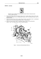
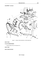
Remove screw (Figure 1, Item 12) and washer (Figure 1, Item 11) from alternator link (Figure 1, Item 10).
2.
Loosen two screws (Figure 1, Item 2) and pivot alternator (Figure 1, Item 1) upward to access terminal cover
(Figure 1, Item 20).
3.
Remove two screw assembled lockwashers (Figure 1, Item 21) and terminal cover (Figure 1, Item 20) from
alternator (Figure 1, Item 1). Discard screw assembled lockwashers.
NOTE
•
Sealant must be removed before removing wires.
•
Tag all leads for installation.
4.
Remove screw (Figure 1, Item 19), lockwasher (Figure 1, Item 18), negative wire (Figure 1, Item 25), and
capacitor lead (Figure 1, Item 22) from alternator (Figure 1, Item 1). Discard lockwasher.
5.
Remove nut (Figure 1, Item 17), lockwasher (Figure 1, Item 16), lead wire 566 (Figure 1, Item 24), and capacitor
(Figure 1, Item 15) from alternator (Figure 1, Item 1). Discard lockwasher.
6.
Remove locknut (Figure 1, Item 14), lockwasher (Figure 1, Item 13), positive wire (Figure 1, Item 23) from
alternator (Figure 1, Item 1). Discard lockwasher.
7.
Disconnect wire (Figure 1, Item 26) from connector (Figure 1, Item 27).
WARNING
Alternator is heavy. Assistant will help with alternator removal. Failure to comply may result
in injury or death to personnel.
8.
Remove two screws (Figure 1, Item 2), washers (Figure 1, Item 3), and alternator (Figure 1, Item 1) from
brackets (Figure 1, Items 4 and 6). Move bracket (Figure 1, Item 4) to one side.
9.
Remove four screws (Figure 1, Item 7) and bracket (Figure 1, Item 6) from engine (Figure 1, Item 5).
10.
Remove screw (Figure 1, Item 8), washer (Figure 1, Item 9), and alternator link (Figure 1, Item 10) from engine
(Figure 1, Item 5).
TM 9-2320-272-23-2
0301
0301-2
Back to Top


