TM-9-2320-272-23-2 - Page 1103 of 1417
REMOVAL
1.
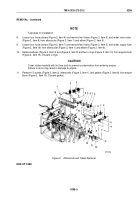
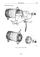
Remove two screw assembled lockwashers (Figure 1, Item 10) and terminal cover (Figure 1, Item 9) from
alternator (Figure 1, Item 15). Discard screw assembled lockwashers.
2.
Remove two screws (Figure 1, Item 8), lockwashers (Figure 1, Item 7), and wire retaining strap
(Figure
1,
Item
6) from alternator (Figure 1, Item 15). Discard lockwashers.
NOTE
•
Sealant must be removed before removing wires.
•
Tag all wires for installation.
3.
Remove screw (Figure 1, Item 1), lockwasher (Figure 1, Item 19), and wire (Figure 1, Item 18) from alternator
(Figure 1, Item 15). Discard lockwasher.
4.
Remove nut (Figure 1, Item 5), lockwasher (Figure 1, Item 4), washer (Figure 1, Item 3), and wire
(Figure
1,
Item
2) from alternator (Figure 1, Item 15). Discard lockwasher.
5.
Remove nut (Figure 1, Item 11), lockwasher (Figure 1, Item 12), washer (Figure 1, Item 13), and wire
(Figure
1,
Item
14) from alternator (Figure 1, Item 15). Discard lockwasher.
6.
Disconnect connector (Figure 1, Item 16) from alternator (Figure 1, Item 15).
7.
Remove and discard tiedown strap (Figure 1, Item 17).
10
14
15
16
17
18
19
1
2
3
4
5
6
7
8
9
11
12
13
M0175DAA
Figure 1.
Alternator and Mounting Bracket Removal.
TM 9-2320-272-23-2
0300
0300-2
Back to Top


