TM-9-2320-272-23-2 - Page 1373 of 1417
INSTALLATION
1.
Install pad (Figure 3, Item 14), contact brush (Figure 3, Item 13), and capacitor (Figure 3, Item 20) on steering
column (Figure 3, Item 18) with two screws (Figure 3, Item 19).
2.
Install boot (Figure 3, Item 25) and wire (Figure 3, Item 21) on contact brush cover (Figure 3, Item 24) with
screw (Figure 3, Item 11), two washers (Figure 3, Item 3), washer (Figure 3, Item 6), and nut
(Figure
3,
Item
2).
3.
Install wire (Figure 3, Item 21) and capacitor (Figure 3, Item 20) on contact brush (Figure 3, Item 13) with
locktab (Figure 3, Item 22) and screw (Figure 3, Item 23).
4.
Install gasket (Figure 3, Item 12), contact brush cover (Figure 3, Item 24), and ground wire (Figure 3, Item 5)
on steering column (Figure 3, Item 18) with four screws (Figure 3, Item 4).
5.
Connect connector (Figure 3, Item 1) and boot (Figure 3, Item 25) to brush cover (Figure 3, Item 24).
6.
Turn steering column (Figure 3, Item 18) until contact brush cover (Figure 3, Item 24) is toward firewall
(Figure
3,
Item
17).
7.
Position floormat (Figure 3, Item 15) against steering column (Figure 3, Item 18) on cab floor
(Figure
3,
Item
16).
8.
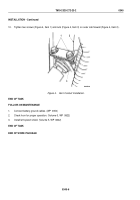
Tighten two screws (Figure 3, Item 9) on steering column bracket (Figure 3, Item 10).
NOTE
Step (9) applies to M931 and M932 vehicles only.
9.
Tighten two screws (Figure 3, Item 7) on trailer brake control valve bracket (Figure 3, Item 8).
TM 9-2320-272-23-2
0345
0345-4
Back to Top


