TM-9-2320-272-23-2 - Page 1375 of 1417
INSTALLATION - Continued
10.
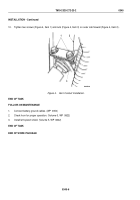
Tighten two screws (Figure 4, Item 1) and nuts (Figure 4, Item 3) on outer cab firewall (Figure 4, Item 2).
1
2
3
M0234DAA
Figure 4.
Horn Contact Installation.
END OF TASK
FOLLOW-ON MAINTENANCE
1.
Connect battery ground cables. (WP
0350)
2.
Check horn for proper operation. (Volume 5, WP
0822)
3.
Install left splash shield. (Volume 5, WP
0822)
END OF TASK
END OF WORK PACKAGE
TM 9-2320-272-23-2
0345
0345-6
Back to Top


