TM-9-2320-272-23-2 - Page 165 of 1417
ABS - CODE YEHd 63 (RIGHT SIDE - YELLOW CHANNEL) - Continued
STEP
3.
IS THE MAIN WIRING HARNESS OK?
a.
Ensure battery and start switches are in the OFF position.
b.
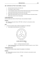
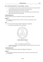
Connect hold solenoid cable connector at front relay valve.
T0950DAA
SENSOR 2A HI
SENSOR 2B LOW
NOT USED
NOT USED
NOT USED
BLUE (LEFT) SOLENOID COMMON
YELLOW (RIGHT) SOLENOID HOLD
YELLOW (RIGHT) SOLENOID COMMON
NOT USED
NOT USED
LAMP -
B- GROUND
NOT USED
DDU B-
DIAGNOSTIC OUTPUT
DDU B+
20
21
11
10
1
2
12
13
22
23
14
4
3
5
15
24
25
16
6
7
17
26
27
18
8
9
19
28
DIAGNOSTIC INPUT
LAMP +
YELLOW (RIGHT) SOLENOID PUMP
BLUE (LEFT) SOLENOID HOLD
BLUE (LEFT) SOLENOID DUMP
SENSOR 2B HI
SENSOR 2A LOW
B+ PERM
NOT USED
NOT USED
NOT USED
IGNITION SWITCHED B+
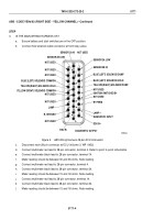
Figure 3.
ABS Wiring Harness 28-pin ECU Connector.
c.
Disconnect main 28-pin connector at ECU (Volume 3, WP
0452).
d.
Connect multimeter red lead to 28-pin connector, terminal 4. Refer to point to point schematics.
e.
Connect multimeter black lead to 28-pin connector, terminal 14.
f.
Meter reading should be between 30 and 36 ohms. Note reading.
g.
Connect multimeter red lead to 28-pin connector, terminal 4.
h.
Connect multimeter black lead to 28-pin connector, terminal 24.
i.
Meter reading should be between 15 and 18 ohms. Note reading.
j.
Connect multimeter red lead to 28-pin connector, terminal 14.
k.
Connect multimeter black lead to 28-pin connector, terminal 24.
l.
Meter reading should be between 15 and 18 ohms. Note reading.
TM 9-2320-272-23-2
0171
0171-4
Back to Top


