TM-9-2320-272-23-2 - Page 384 of 1417
Table
1.
Field Preventive Maintenance Checks and Services - Continued.
ITEM
NO.
INTERVAL
ITEM TO BE
CHECKED OR
SERVICED
PROCEDURE
EQUIPMENT
NOT READY/
AVAILABLE IF:
I00011DAA
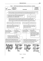
Build up air pressure in primary and secondary air systems to 50 to 60 psi (344.75 to 413.70 kPa). Trace the air line
from wet tank (Figure 3, Item 3) to drainvalve (Figure 3, Item 5). Open the drainvalve (Figure 3, Item 5).
Air pressure drops to zero in either primary (Figure 3, Item 6) or
secondary (Figure 3, Item 2) air tanks. Replace faulty check
valve(s) (Figure 3, Item 1) at a±ected tank(s).
Air systems maintain pressure.
Build up pressure in the primary and secondary air system to 50 to 60 psi (344.75 to 413.70 kPa).
Remove air gauge line at the primary (lower) air gauge port (Figure 3, Item 9) of the treadle valve
(Figure 3, Item 7). Do not allow air to bleed out slowly as this may a±ect results. Observe the gauges.
Secondary air gauge (Figure 3, Item 7) drops to zero.
Primary air gauge (Figure 3, Item 8) drops to zero.
Follow air line from primary air tank (Figure 3,
Item 6) to drainvalve (Figure 3, Item 4). Open
drainvalve (Figure 3, Item 4).
Air pressure released
when drainvalve (Figure 3,
Item 4) is opened.
Follow air line from primary air tank (Figure 3,
Item 6) to drainvalve (Figure 3, Item 4). Open
drainvalve (Figure 3, Item 4).
Air pressure released
when drainvalve (Figure 3,
Item 4) is opened.
No air pressure
released when drain-
valve (Figure 3, Item 4)
is opened.
No air pressure
released when drain-
valve (Figure 3, Item 4)
is opened. Air lines are installed
properly. Inspection is complete.
Reconnect lower air gauge line at
treadle valve (Figure 3, Item 7).
See View D below.
Switch and connect treadle supply hoses at the
primary (Figure 3, Item 6) and secondary (Figure 3, Item 2)
air tanks; and the primary and secondary air gauge lines at
the treadle valve (Figure 3, Item 7). See View A below.
Switch and connect treadle supply hoses at the
primary (Figure 3, Item 6) and secondary (Figure 3, Item 2)
air tanks. Reconnect lower air gauge line at treadle
valve (Figure 3, Item 7). See View C below.
Switch and connect the primary and
secondary air gauge lines at the treadle
valve (Figure 3, Item 7). See View B below.
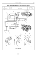
Figure 2.
Air System.
TM 9-2320-272-23-2
0208
0208-5
Back to Top

