TM-9-2320-272-23-2 - Page 553 of 1417
INSTALLATION
1.
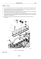
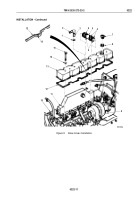
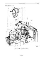
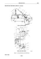
Install seal (Figure 5, Item 8) and filler cap (Figure 5, Item 7) on valve cover (Figure 5, Item 13).
CAUTION
Valve cover gasket must extend into overlap area. Trim excess overlap, and do not stretch
valve cover gasket. Damage to gasket may result.
2.
Turn valve cover (Figure 5, Item 13) upside down and install valve cover gasket (Figure 5, Item 12) on valve
cover, overlapping ends in the overlap area (Figure 5, Item 16). Apply gasket sealant to overlap area.
3.
Compress locking tabs (Figure 5, Item 3) of vent connector (Figure 5, Item 2), and install o-ring
(Figure
5,
Item
1) and vent connector on valve cover (Figure 5, Item 13).
4.
Install valve cover (Figure 5, Item 13) on cylinder head (Figure 5, Item 10) with six o-rings
(Figure
5,
Item
12) and screws (Figure 5, Item 15). Tighten screws 18 lb-ft (24 N·m).
CAUTION
Ensure covers are removed from turbocharger intake output port and aftercooler inlet port
prior to installing crossover tube. Failure to do so may cause damage to equipment.
5.
Install crossover tube (Figure 5, Item 5) by sliding two hoses (Figure 5, Item 6) onto turbocharger
(Figure
5,
Item
9) and aftercooler (Figure 5, Item 11) and tighten four clamps (Figure 5, Item 4).
TM 9-2320-272-23-2
0222
0222-10
Back to Top

