TM-9-2320-272-23-2 - Page 558 of 1417
INSTALLATION - Continued
12.
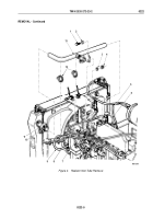
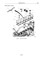
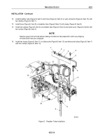
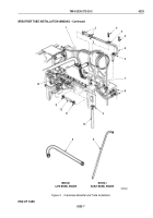
Install breather tube (Figure 8, Item 3) and hose (Figure 8, Item 2) on vent connector (Figure 8, Item 13) with
two clamps (Figure 8, Item 1).
13.
Install hose (Figure 8, Item 9) on breather tube (Figure 8 Item 3) with clamp (Figure 8, Item 8).
14.
Install two clamps (Figure 8, Item 5) on breather tube (Figure 8, Item 3) and valve cover (Figure 8, Item 6) with
two screws (Figure 8, Item 4).
NOTE
Remove plugs from all lines before making connections. Be prepared to catch any dripping
of fluids when lines are uncapped.
15.
Install two hoses (Figure 8, Item 11) on aftercooler (Figure 8, Item 12) and aftercooler tubes (Figure 8, Item 7)
with four clamps (Figure 8, Item 10).
M0021DAA
1
2
1
3
4
5
5
6
7
8
9
10
11
13
13
Figure 8.
Breather Tube Installation.
TM 9-2320-272-23-2
0222
0222-15
Back to Top

