TM-9-2320-272-23-2 - Page 567 of 1417
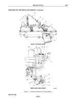
BREATHER AND TUBE INSTALLATION (M939/A1)
NOTE
Perform Steps (1) and (2) if breather was removed.
1.
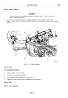
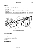
Apply adhesive sealant to mating surfaces of crankcase breather (Figure 4, Item 1) an valve cover
(Figure
4,
Item
7).
2.
Install crankcase breather (Figure 4, Item 1) on valve cover (Figure 4, Item 7) and align with mark.
NOTE
Perform Steps (3) and (4) on vehicles with late model engines and Steps (5) through (7) on
vehicles with early model engines.
3.
Apply antiseize compound to threads of elbow (Figure 4, Item 5) and install on air connector
(Figure
4,
Item
6).
4.
Install two breather hoses (Figure 4, Item 3) and breather tube (Figure 4, Item 4) on elbow (Figure 4, Item 5)
and crankcase breather (Figure 4, Item 1) with four hose clamps (Figure 4, Item 2).
5.
Install breather hose (Figure 4, Item 17) and breather tube (Figure 4, Item 15) on crankcase breather
(Figure
4,
Item
1) with two clamps (Figure 4, Item 16).
6.
Install mounting bracket (Figure 4, Item 9) on engine (Figure 4, Item 8) with lockwasher (Figure 4, Item 11)
and screw (Figure 4, Item 12).
7.
Install clamp (Figure 4, Item 13) on mounting bracket (Figure 4, Item 9) and breather tube (Figure 4, Item 15)
with screw (Figure 4, Item 10) and locknut (Figure 4, Item 14).
TM 9-2320-272-23-2
0223
0223-8
Back to Top

