TM-9-2320-272-23-2 - Page 801 of 1417
REMOVAL - Continued
12.
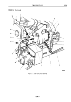
Remove nut (Figure 3, Item 5), screw (Figure 3, Item 1), and two clamps (Figure 3, Item 4) from fuel supply
line (Figure 3, Item 2) and fuel return line (Figure 3, Item 3).
13.
Remove nut (Figure 3, Item 11), screw (Figure 3, Item 8), and two clamps (Figure 3, Item 10) from fuel supply
line (Figure 3, Item 2), fuel return line (Figure 3, Item 3), and bracket (Figure 3, Item 7).
NOTE
Perform Step (14) if bracket is damaged.
14.
Remove nut (Figure 3, Item 9), screw (Figure 3, Item 6), and bracket (Figure 3, Item 7) from frame rail
(Figure
3,
Item
12).
15.
Remove nut (Figure 3, Item 15), screw (Figure 3, Item 13), and two clamps (Figure 3, Item 14) from fuel supply
line (Figure 3, Item 2) and fuel return line (Figure 3, Item 3).
16.
Disconnect two tubing nuts (Figure 3, Item 17) from fittings (Figure 3, Item 18) and remove rear half of fuel
supply line (Figure 3, Item 2) and fuel return line (Figure 3, Item 3) from fuel tank (Figure 3, Item 16).
NOTE
Perform Steps (17) through (19) for vehicles equipped with dual fuel tanks.
17.
Remove nut (Figure 3, Item 22) and screw (Figure 3, Item 24) from two clamps (Figure 3, Item 23).
18.
Disconnect two tubing nuts (Figure 3, Item 21) from adapter fittings (Figure 3, Item 20) on selector valve
(Figure
3,
Item
19).
19.
Remove fuel supply line (Figure 3, Item 2) and fuel return line (Figure 3, Item 3) from adapter fittings
(Figure
3,
Item
20).
TM 9-2320-272-23-2
0254
0254-6
Back to Top


