TM-9-2320-272-23-2 - Page 805 of 1417
INSTALLATION - Continued
8.
Install clamp (Figure 5, Item 2) on fuel return line (Figure 5, Item 5) with screw (Figure 5, Item 1) and nut
(Figure
5,
Item
3).
9.
Install front half of fuel supply line (Figure 5, Item 6) and rear half of fuel supply line (Figure 5, Item 6) on tee
(Figure 5, Item 10) with tubing nuts (Figure 5, Item 9).
10.
Install two clamps (Figure 5, Item 7) on fuel supply line (Figure 5, Item 6) and fuel return line
(Figure
5,
Item
5) with screw (Figure 5, Item 4) and nut (Figure 5, Item 8).
11.
Install two clamps (Figure 5, Item 12) on fuel supply line (Figure 5, Item 6) and fuel return line
(Figure
5,
Item
5) with screw (Figure 5, Item 11) and nut (Figure 5, Item 13).
12.
Install clamp (Figure 5, Item 15) on fuel supply line (Figure 5, Item 6) with screw (Figure 5, Item 14) and nut
(Figure 5, Item 16).
13.
Install clamp (Figure 5, Item 18) on fuel return line (Figure 5, Item 5) with screw (Figure 5, Item 17) and nut
(Figure 5, Item 19).
1
2
3
4
5
6
7
8
9
10
9
6
14
16
15
6
17
5
18
19
12
13
5
6
11
M0072DAA
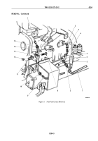
Figure 5.
Fuel Return and Supply Lines Installation.
14.
Install fuel return hose (Figure 6, Item 14) on fitting (Figure 6, Item 1) and fuel return line (Figure 6, Item 9)
with two hose clamps (Figure 6, Item 10).
TM 9-2320-272-23-2
0254
0254-10
Back to Top


