TM-9-2320-272-23-3 - Page 1025 of 1469
REMOVAL
1.
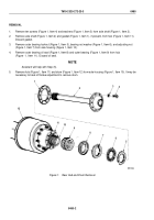
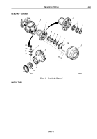
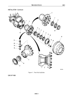
Remove brake drum (Figure 1, Item 11) from hub (Figure 1, Item 2).
2.
Remove ten screws (Figure 1, Item 12) and washers (Figure 1, Item 13) from drive flange (Figure 1, Item 9).
3.
Install two screws (Figure 1, Item 12) on threaded holes (Figure 1, Item 10) of drive flange (Figure 1, Item 9).
Tighten screws (Figure 1, Item 12) until drive flange (Figure 1, Item 9) separates from hub (Figure 1, Item 2).
4.
Remove drive flange (Figure 1, Item 9) from hub (Figure 1, Item 2) and remove two screws (Figure 1, Item 12)
from drive flange.
NOTE
Tag inner and outer bearings for installation.
5.
Remove outer bearing nut (Figure 1, Item 6) and washer (Figure 1, Item 5) from spindle (Figure 1, Item 1).
6.
Remove nut (Figure 1, Item 4) and outer bearing (Figure 1, Item 3) from spindle (Figure 1, Item 1).
NOTE
Assistant will help with Step (7).
7.
Remove hub (Figure 1, Item 2) from spindle (Figure 1, Item 1).
8.
Remove snapring (Figure 1, Item 8) and two air seals (Figure 1, Item 7) from hub (Figure 1, Item 2). Discard
air seals.
9.
Remove screw (Figure 1, Item 20), ferrule (Figure 1, Item 19), tee (Figure 1, Item 18), and gasket
(Figure
1,
Item 17) from hub (Figure 1, Item 2). Discard ferrule and gasket.
10.
Remove hub seal (Figure 1, Item 16) and inner bearing (Figure 1, Item 15) from rear of hub (Figure 1, Item 2).
Discard hub seal.
11.
For General Cleaning Instructions, refer to (Volume 5, WP
0819).
12.
For General Inspection Instructions, refer to (Volume 5, WP
0819).
13.
Inspect inner (Figure 1, Item 15) and outer (Figure 1, Item 3) bearings in accordance with TM 9-214. Replace
bearings and bearings cups if either is damaged.
14.
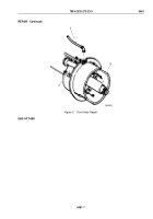
Inspect hub (Figure 1, Item 2), drive flange (Figure 1, Item 9), and plastic sleeving (Figure 1, Item 14) for cracks,
grooves, scores, and elongated holes. Replace part(s) if cracked or holes are elongated. Notify your supervisor
if grooved or scored.
15.
Inspect seal surface of spindle (Figure 1, Item 1) for extensive rust, scratches, and grooves. Repair spindle if
rusted, scratched, or grooved.
TM 9-2320-272-23-3
0481
0481-2
Back to Top

