TM-9-2320-272-23-3 - Page 1031 of 1469
INSTALLATION
1.
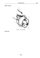
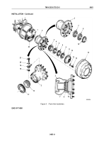
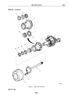
Using long end of seal inserter, install air seal (Figure 4, Item 7) on hub (Figure 4, Item 2) with spring facing
out. Ensure air seal is seated properly in hub.
2.
Using short end of seal inserter, install air seal (Figure 4, Item 8) on hub (Figure 4, Item 2) with spring facing
out. Ensure air seal is seated properly in hub.
3.
Install snapring (Figure 4, Item 10) on hub (Figure 4, Item 2).
4.
Install gasket (Figure 4, Item 18), tee (Figure 4, Item 19), ferrule (Figure 4, Item 20), and screw
(Figure
4,
Item
21) on hub (Figure 4, Item 2). Finger-tighten screw.
5.
Align drive flange (Figure 4, Item 12) with tee (Figure 4, Item 19) and install drive flange on hub
(Figure
4,
Item
2) with two screws (Figure 4, Item 14).
6.
Tighten screw (Figure 4, Item 21) 35 lb-ft (48 N·m).
7.
Install two screws (Figure 4, Item 14) in threaded holes (Figure 4, Item 11) of drive flange (Figure 4, Item 12).
8.
Remove two screws (Figure 4, Item 14) and drive flange (Figure 4, Item 12) from hub (Figure 4, Item 2).
CAUTION
Ensure bearings are matched with bearing cups before installation. Damage to
bearings
and/or
bearing cups may result.
NOTE
•
Pack inner and outer bearings with automotive and artillery grease prior to installation.
•
Pack inner rubber section of hub seal with automotive and artillery grease.
9.
Install inner bearing (Figure 4, Item 16) and hub seal (Figure 4, Item 17) on hub (Figure 4, Item 2).
CAUTION
Do not allow hub assembly to slide directly over threaded end of spindle. Damage to air seals
may result.
NOTE
Assistant will help with Step (10).
10.
Install hub (Figure 4, Item 2), outer bearing (Figure 4, Item 3), and bearing adjusting nut (Figure 4, Item 5) on
spindle (Figure 4, Item 22).
11.
While rotating hub (Figure 4, Item 2), tighten bearing adjusting nut (Figure 4, Item 5) 50 lb-ft (68 N·m).
12.
Back out bearing adjusting nut (Figure 4, Item 5) 1/8 to 1/4 turn so washer (Figure 4, Item 6) can be aligned
with slot in spindle (Figure 4, Item 22) and adjusting nut locking pin (Figure 4, Item 4).
13.
Install washer (Figure 4, Item 6) and nut (Figure 4, Item 9) on spindle (Figure 4, Item 22). Tighten nut
250
to
400
lb-ft (339 to 542 N·m).
14.
Apply silicone rubber adhesive to sealing surfaces of hub (Figure 4, Item 2) and drive flange
(Figure
4,
Item
9).
15.
Align drive flange (Figure 4, Item 12) with tee (Figure 4, Item 19), and install drive flange on driveshaft
(Figure
4,
Item
1) and hub (Figure 4, Item 2) with ten washers (Figure 4, Item 13) and screws
(Figure 4, Item 14). Tighten screws 60 to 100 lb-ft (81 to 136 N·m).
16.
Install brake drum (Figure 4, Item 15) on hub (Figure 4, Item 2).
TM 9-2320-272-23-3
0481
0481-8
Back to Top


