TM-9-2320-272-23-3 - Page 1035 of 1469
REMOVAL
1.
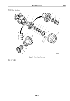
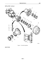
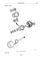
Remove brake drum (Figure 1, Item 9) from hub (Figure 1, Item 3).
2.
Remove ten screws (Figure 1, Item 8), lockwashers (Figure 1, Item 7), and axle shaft (Figure 1, Item 6) from
hub (Figure 1, Item 3). Discard lockwashers.
NOTE
Tag inner and outer bearings for installation.
3.
Remove outer bearing nut (Figure 1, Item 10) and washer (Figure 1, Item 11) from spindle (Figure 1, Item 5).
4.
Remove bearing adjusting nut (Figure 1, Item 12) and outer bearing (Figure 1, Item 13) from spindle
(Figure
1, Item 5).
CAUTION
Do not allow hub assembly to slide directly over threaded end of spindle. Damage to air seals
may result.
NOTE
Assistant will help with Step (5).
5.
Remove hub (Figure 1, Item 3) from spindle (Figure 1, Item 5).
6.
Remove oil seal (Figure 1, Item 4) and inner bearing (Figure 1, Item 14) from hub (Figure 1, Item 3). Discard
oil seal.
7.
Remove snapring (Figure 1, Item 1) and two air seals (Figure 1, Item 2) from hub (Figure 1, Item 3). Discard
air seals.
TM 9-2320-272-23-3
0482
0482-2
Back to Top

