TM-9-2320-272-23-3 - Page 1041 of 1469
REPAIR
1.
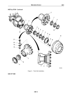
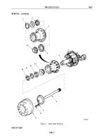
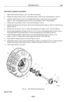
Using bearing punch, remove outer bearing cup (Figure 4, Item 4) from hub (Figure 4, Item 5) by tapping
alternately on outer edges of bearing cup. Discard outer bearing cup.
2.
Using bearing punch, remove inner bearing cup (Figure 4, Item 1) from hub (Figure 4, Item 5) by tapping
alternately on outer edges of inner bearing cup.
3.
Remove plastic sleeve (Figure 4, Item 6) from hub (Figure 4, Item 5) by splitting and prying plastic sleeve from
hub. Discard plastic sleeve.
NOTE
Bearings and bearing cups must be replaced as a matched set.
4.
Install outer bearing cup (Figure 4, Item 4) on hub (Figure 4, Item 5). Ensure outer bearing cup is properly
seated on hub.
5.
Install plastic sleeve (Figure 4, Item 6) on hub (Figure 4, Item 5).
6.
Install inner bearing cup (Figure 4, Item 1) on hub (Figure 4, Item 5). Ensure inner bearing cup is seated properly
on hub.
NOTE
•
Perform Steps (7) through (9) if slinger or studs failed inspection.
•
Use left-hand threaded studs for hub mounted on the left side of vehicle, and right-hand
threaded studs for hubs mounted on the right side of vehicle.
7.
Remove studs (Figure 4, Item 2) and slinger (Figure 4, Item 3) from hub (Figure 4, Item 5).
8.
Remove damaged studs (Figure 4, Item 2) from slinger (Figure 4, Item 3) and hub (Figure 4, Item 5). Discard
studs and slinger.
9.
Position slinger (Figure 4, Item 3) on hub (Figure 4, Item 5), and install with studs (Figure 4, Item 2).
TM 9-2320-272-23-3
0482
0482-8
Back to Top

