TM-9-2320-272-23-3 - Page 1049 of 1469
REAR WHEEL BEARING ADJUSTMENT
1.
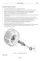
Raise vehicle until tires (Figure 2, Item 1) are clear off the ground.
2.
Remove ten screws (Figure 2, Item 7) and washers (Figure 2, Item 6) from axle shaft (Figure 2, Item 5).
3.
Install two screws (Figure 2, Item 7) into threaded holes (Figure 2, Item 8) and remove axle shaft
(Figure
2,
Item
5) and gasket (Figure 2, Item 4) from hub (Figure 2, Item 1). Discard gasket.
4.
Remove two screws (Figure 2, Item 7) from axle shaft (Figure 2, Item 5).
5.
Remove outer bearing locknut (Figure 2, Item 3) and outer bearing washer (Figure 2, Item 2) from axle housing
(Figure 2, Item 9).
6.
While turning hub (Figure 2, Item 11), tighten bearing adjusting nut (Figure 2, Item 10) 50 lb-ft (68 N·m).
7.
Back out bearing adjusting nut (Figure 2, Item 10) 1/6 to 1/4 turn so outer bearing washer (Figure 2, Item 2)
can be positioned to axle housing (Figure 2, Item 9) and adjusting nut insert (Figure 2, Item 12).
8.
Install outer bearing washer (Figure 2, Item 2) and outer bearing locknut (Figure 2, Item 3) on hub
(Figure
2,
Item
11). Tighten outer bearing locknut 250 to 400 lb-ft (339 to 542 N·m).
9.
Apply sealant to mating surfaces of axle shaft (Figure 2, Item 5).
10.
Install gasket (Figure 2, Item 4) and axle shaft (Figure 2, Item 5) on hub (Figure 2, Item 11) with ten washers
(Figure 2, Item 6) and screws (Figure 2, Item 7). Tighten screws 60 to 100 lb-ft (81
to
136
N·m).
11.
Lower vehicle until tire is on ground.
M5022DAA
2
3
4
5
6
7
8
11
12
10
9
1
Figure 2.
Rear Wheel Bearing Adjustment.
END OF TASK
TM 9-2320-272-23-3
0483
0483-4
Back to Top


