TM-9-2320-272-23-3 - Page 1113 of 1469
REMOVAL
NOTE
Before removing steering wheel columns, make sure front wheels are straight ahead for
proper steering wheel alignment.
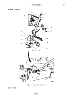
1.
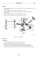
Remove nut (Figure 1, Item 9), lockwasher (Figure 1, Item 10), and screw (Figure 1, Item 12) from universal
joint (Figure 1, Item 11). Discard lockwasher.
2.
Remove two locknuts (Figure 1, Item 14), screws (Figure 1, Item 7), washers (Figure 1, Item 8), and lower
mounting clamp (Figure 1, Item 6) from upper steering column (Figure 1, Item 3) and firewall
(Figure
1,
Item
13). Discard locknuts.
NOTE
Mark upper support clamp location on steering column for installation.
3.
Remove two screws (Figure 1, Item 5) and upper support clamp (Figure 1, Item 4) from upper steering column
(Figure 1, Item 3) and instrument panel (Figure 1, Item 1).
4.
Remove upper steering column (Figure 1, Item 3) from universal joint (Figure 1, Item 11) and lift out through
floorboard (Figure 1, Item 15).
5.
Slide two clamp bushings (Figure 1, Item 2) off upper steering column (Figure 1, Item 3).
6.
Remove nut (Figure 1, Item 16), lockwasher (Figure 1, Item 17), screw (Figure 1, Item 19), and U-joint
(Figure
1, Item 18) from steering gear input shaft (Figure 1, Item 20). Discard lockwasher.
TM 9-2320-272-23-3
0494
0494-2
Back to Top

