TM-9-2320-272-23-3 - Page 1159 of 1469
REMOVAL
NOTE
Have container ready to catch hydraulic fluid.
1.
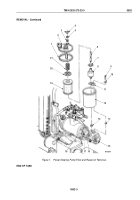
Loosen clamp (Figure 1, Item 17) and remove hose (Figure 1, Item 18) from tube (Figure 1, Item 16).
2.
Remove wing nut (Figure 1, Item 4), washer (Figure 1, Item 5), gasket (Figure 1, Item 3), lid
(Figure
1,
Item
2), and gasket (Figure 1, Item 1) from stud (Figure 1, Item 6) and reservoir
(Figure
1,
Item
12). Discard gaskets.
3.
Remove spring (Figure 1, Item 21), filter cap (Figure 1, Item 20), filter (Figure 1, Item 19), and packing
(Figure
1, Item 7) from stud (Figure 1, Item 6) and reservoir (Figure
1,
Item
12). Discard filter and packing.
4.
Remove stud (Figure 1, Item 6) and valve (Figure 1, Item 8) from plate (Figure 1, Item 11).
5.
Remove two screws (Figure 1, Item 9), lockwashers (Figure 1, Item 10), plate (Figure 1, Item 11), and reservoir
(Figure 1, Item 12) from power steering pump (Figure 1, Item 15). Discard lockwashers.
6.
Remove gaskets (Figure 1, Items 13 and 14) from power steering pump (Figure 1, Item 15). Discard gaskets.
7.
Clean inside of reservoir (Figure 1, Item 12) with crocus cloth.
TM 9-2320-272-23-3
0502
0502-2
Back to Top


