TM-9-2320-272-23-3 - Page 1151 of 1469
INSTALLATION - Continued
11.
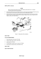
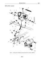
Press friction washer (Figure 4, Item 9) and lockwasher (Figure 4, Item 11) into slot on retainer
(Figure
4,
Item
4).
12.
Press three nylon balls (Figure 4, Item 10) into indentations on retainer (Figure 4, Item 4).
13.
Aligning timing marks (Figure 4, Items 1 and 2), position seal (Figure 4, Item 7) and pitman arm
(Figure
4,
Item
3) on output shaft (Figure 4, Item 8).
14.
Install retainer (Figure 4, Item 4) into output shaft (Figure 4, Item 8) until drag of friction washer
(Figure
4,
Item
9) is felt.
15.
Align long tabs (Figure 4, Item 5) to notches in pitman arm (Figure 4, Item 3) and bend tabs in notches. Back
out retainer (Figure 4, Item 4) up to 1/2 turn as necessary for tabs alignment.
16.
Tighten retainer (Figure 4, Item 4) 225 lb-ft (305 N·m).
17.
Bend two short tabs (Figure 4, Item 6) into notches on retainer (Figure 4, Item 4). Tighten retainer if necessary
to align tabs with notches of retainer.
11
9
4
10
1
8
7
2
3
4
5
6
M3209DAA
Figure 4.
Steering Gear (Sheppard) Assembly (M939A2).
TM 9-2320-272-23-3
0500
0500-8
Back to Top


