TM-9-2320-272-23-3 - Page 1147 of 1469
REMOVAL - Continued
CAUTION
Cap or plug all openings immediately after disconnecting lines and hoses to prevent
contamination. Failure to do so may result in steering system damage.
NOTE
•
Have container ready to catch oil from disconnected lines.
•
Tag all hydraulic lines and fittings for installation.
6.
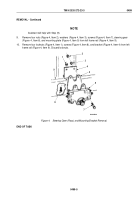
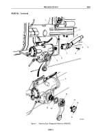
Disconnect oil pressure line (Figure 2, Item 4) and oil return line (Figure 2, Item 9) from adapter elbow
(Figure
2,
Item
3) and adapter (Figure 2, Item 8).
7.
Disconnect assist cylinder pressure lines (Figure 2, Items 14 and16) from adapter elbow (Figure 2, Item 15)
and elbow (Figure 2, Item 13).
8.
Remove adapter elbow (Figure 2, Item 3) and adapter (Figure 2, Item 8) from steering gear (Figure 2, Item 6).
9.
Remove o-rings (Figure 2, Items 5 and 7) from adapter elbow (Figure 2, Item 3) and adapter
(Figure
2,
Item
8). Discard o-rings.
NOTE
Perform Steps (10) through (12) if old steering gear is to be reused.
10.
Remove elbow (Figure 2, Item 1) and adapter elbow (Figure 2, Item 15) from front of steering gear
(Figure
2,
Item
6).
11.
Remove elbow (Figure 2, Item 13), line (Figure 2, Item 12), and adapter (Figure 2, Item 11) from bottom rear
of steering gear (Figure 2, Item 6).
12.
Remove o-rings (Figure 2, Items 2 and 10) from elbow (Figure 2, Item 1) and adapter (Figure 2, Item 11).
Discard o-rings.
NOTE
Assistant will help with Step (13).
13.
Remove four locknuts (Figure 2, Item 17), washers (Figure 2, Item 18), screws (Figure 2, Item 21), steering
gear (Figure 2, Item 6), and mounting plate (Figure 2, Item 20) from left frame rail (Figure 2, Item 23).
Discard
locknuts.
14.
Remove four locknuts (Figure 2, Item 24), screws (Figure 2, Item 22), and mounting bracket
(Figure
2,
Item
19) from left frame rail (Figure 2, Item 23). Discard locknuts.
TM 9-2320-272-23-3
0500
0500-4
Back to Top


