TM-9-2320-272-23-3 - Page 1145 of 1469
REMOVAL
NOTE
Ensure front wheels are aligned straight ahead.
1.
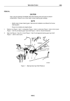
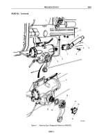
Remove nut (Figure 1, Item 1), lockwasher (Figure 1, Item 2), and screw (Figure 1, Item 6) from sleeve
(Figure
1,
Item
7) of universal joint (Figure 1, Item 5). Discard lockwasher.
2.
Using a chisel, open slot (Figure 1, Item 3) in sleeve (Figure 1, Item 7) of universal joint (Figure 1, Item 5) and
pull lower steering column (Figure 1, Item 4) off steering gear input shaft (Figure 1, Item 8).
3.
Bend two long tabs (Figure 1, Item 12) of retainer (Figure 1, Item 11) out of notches in pitman arm
(Figure
1,
Item
10).
4.
Bend two short tabs (Figure 1, Item 13) out of retainer (Figure 1, Item 11) and remove retainer from sector
shaft (Figure 1, Item 15). Discard retainer.
NOTE
Punch alignment marks on sector shaft and pitman arm.
5.
Using puller, remove pitman arm (Figure 1, Item 10) and seal (Figure 1, Item 14) from sector shaft
(Figure
1,
Item
15) of steering gear (Figure 1, Item 9). Discard seal.
TM 9-2320-272-23-3
0500
0500-2
Back to Top

