TM-9-2320-272-23-3 - Page 1135 of 1469
REMOVAL
CAUTION
Cap or plug all openings immediately after disconnecting lines and hoses to prevent
contamination. Failure to do so may result in power steering gear damage.
NOTE
•
Identify type of power steering gear. Removal and installation are different for the two
steering gears.
•
Ensure front wheels are straight ahead.
1.
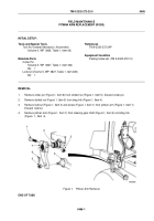
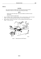
Remove nut (Figure 1, Item 1), lockwasher (Figure 1, Item 2), and screw (Figure 1, Item 4) from U-joint
(Figure
1, Item 5) and steering gear input shaft (Figure 1, Item 6). Discard lockwasher.
2.
Open slot (Figure 1, Item 3) in U-joint (Figure 1, Item 5) and separate steering gear input shaft
(Figure
1,
Item
6) and U-joint.
M10024DAA
1
2
3
6
5
4
Figure 1.
Steering Gear Input Shaft Removal.
TM 9-2320-272-23-3
0499
0499-2
Back to Top

