TM-9-2320-272-23-3 - Page 1129 of 1469
ADJUSTMENT
1.
Position front wheels straight ahead.
2.
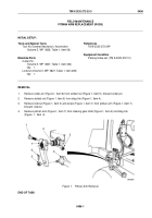
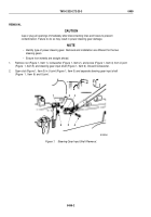
Place alignment device (Figure 1, Item 2) 3 in. (7.6 mm) from outer tire surface of left front wheel
(Figure
1,
Item
1).
3.
Place turning radius gauge (Figure 1, Item 5) against outer tire surface.
4.
Center pointer (Figure 1, Item 4) with wheel (Figure 1, Item 1) and align to 0 degree mark on base scale
(Figure
1,
Item
3).
5.
Turn left front wheel (Figure 1, Item 1) to outward stop and read degrees of travel on base scale
(Figure
1,
Item
3). Scale reading should be 28 degrees. If scale reading is not correct, perform turning
angle
adjustment.
6.
Break welds and remove screw (Figure 1, Item 7) and jamnut (Figure 1, Item 9) from left steering knuckle
(Figure 1, Item 6). Discard screw and jamnut.
7.
Thread nut (Figure 1, Item 9) all the way on screw (Figure 1, Item 7).
8.
Thread screw (Figure 1, Item 7) all the way into tie rod arm (Figure 1, Item 10), then all the way out, until screw
contacts axle housing (Figure 1, Item 8). Screw now becomes turn angle
stop.
9.
While holding screw (Figure 1, Item 7), turn jamnut (Figure 1, Item 9) until it contacts tie rod arm
(Figure
1,
Item
10). Tighten nut 66 to 86 lb-ft (88 to 116 N·m).
NOTE
Repeat task to check right front wheel turning angle adjustment.
10.
Tack-weld nut (Figure 1, Item 9) to screw (Figure 1, Item 7) and back of tie rod arm (Figure 1, Item 10).
TM 9-2320-272-23-3
0497
0497-2
Back to Top


