TM-9-2320-272-23-3 - Page 1123 of 1469
REMOVAL
1.
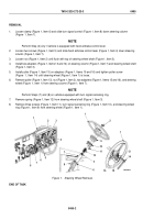
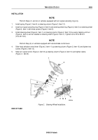
Loosen clamp (Figure 1, Item 6) and slide turn signal control (Figure 1, Item 8) down steering column
(Figure
1, Item 7).
NOTE
Perform Step (2) only if vehicle is equipped with hand airbrake control lever.
2.
Loosen two screws (Figure 1, Item 5) and slide hand airbrake control lever (Figure 1, Item 4) down steering
column (Figure 1, Item 7).
3.
Loosen nut (Figure 1, Item 2) until flush with top of steering wheel shaft (Figure 1, Item 3).
4.
Install two adapters (Figure 1, Items 13 and 14) on steering column (Figure 1, Item 7) and steering wheel shaft
(Figure 1, Item 3).
5.
Install puller (Figure 1, Item 13) on adapters (Figure 1, Items 15 and 16) and tighten puller screw
(Figure
1,
Item
14) until steering wheel (Figure 1, Item 1) is loose.
6.
Remove puller (Figure 1, Item 13), nut (Figure 1, Item 2), two adapters (Figure 1, Items 15 and 16), and steering
wheel (Figure
1, Item 1) from steering column (Figure 1, Item 7).
NOTE
Perform Steps (7) and (8) on vehicles equipped with turn signal canceling ring.
7.
Remove spring (Figure 1, Item 12) from steering wheel shaft (Figure 1, Item 3).
8.
Remove three screws (Figure 1, Item 11), turn signal canceling ring (Figure 1, Item 10), and steering wheel
ring (Figure 1, Item 9) from steering wheel (Figure 1, Item 1).
13
M5023DAA
1
2
3
8
16
4
5
9
6
7
1
1
2
11
8
7
12
6
3
10
15
14
Figure 1.
Steering Wheel Removal.
END OF TASK
TM 9-2320-272-23-3
0495
0495-2
Back to Top


