TM-9-2320-272-23-3 - Page 1138 of 1469
REMOVAL - Continued
NOTE
Assistant will help with Step (9).
9.
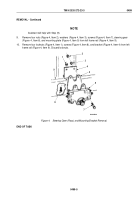
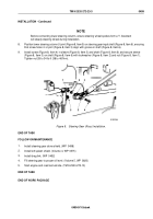
Remove four nuts (Figure 4, Item 2), washers (Figure 4, Item 3), screws (Figure 4, Item 7), steering gear
(Figure
4, Item 6), and mounting plate (Figure 4, Item 5) from left frame rail (Figure 4, Item 9).
10.
Remove four locknuts (Figure 4, Item 1), screws (Figure 4, Item 8), and bracket (Figure 4, Item 4) from left
frame rail (Figure 4, Item 9). Discard locknuts.
M10030DAA
2
1
3
4
5
6
7
9
8
Figure 4.
Steering Geer (Ross) and Mounting Bracket Removal.
END OF TASK
TM 9-2320-272-23-3
0499
0499-5
Back to Top


