TM-9-2320-272-23-3 - Page 1142 of 1469
INSTALLATION - Continued
NOTE
Before connecting lower steering column, ensure steering wheel spokes form a Y. Assistant
will steady steering wheel during installation.
8.
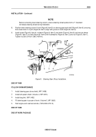
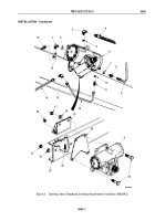
Position lower steering column U-joint (Figure 8, Item 5) on steering gear input shaft (Figure 8, Item 6), ensuring
that screw holes in U-joint (Figure 8, Item 3) align with groove in shaft (Figure 8, Item 6).
9.
Install screw (Figure 8, Item 4) in sleeve (Figure 8, Item 3) and shaft (Figure 8, Item 6) and secure sleeve
(Figure 8, Item 3) on shaft (Figure 8, Item 6) with lockwasher (Figure 8, Item 2) and nut (Figure 8, Item 1).
Tighten nut 28 to 34 lb-ft (38 to 46 N·m).
M10025DAA
1
2
3
6
5
4
Figure 8.
Steering Geer (Ross) Installation.
END OF TASK
FOLLOW-ON MAINTENANCE
1.
Install steering gear stone shield. (WP
0498)
2.
Install left splash shield. (Volume 4, WP
0575)
3.
Install drag link. (WP
0492)
4.
Fill steering gear to proper oil level. (Volume 5, WP
0820)
5.
Start engine and road test vehicle. (TM 9-2320-272-10)
END OF TASK
END OF WORK PACKAGE
TM 9-2320-272-23-3
0499
0499-9/10 blank
Back to Top


