TM-9-2320-272-23-3 - Page 1149 of 1469
INSTALLATION
1.
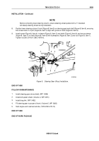
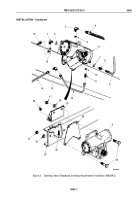
Install mounting bracket (Figure 3, Item 19) on left frame rail (Figure 3, Item 23) with four screws
(Figure
3,
Item
22) and locknuts (Figure 3, Item 24). Do not tighten locknuts.
2.
Install mounting plate (Figure 3, Item 20) and steering gear (Figure 3, Item 6) housing on left frame rail
(Figure
3,
Item
23) and mounting bracket (Figure 3, Item 19) with four screws (Figure 3, Item 21), washers
(Figure 3, Item 18), and locknuts (Figure 3, Item 17). Tighten locknuts 260 to 280 lb-ft (353
to
380
N·m).
3.
Tighten locknuts (Figure 3, Item 24) 60 to 70 lb-ft (81 to 95 N·m).
NOTE
Perform Steps (4), (5), and (6) if old steering gear is to be installed.
4.
Install o-rings (Figure 3, Items 2 and 10) on elbow (Figure 3, Item 1) and adapter (Figure 3, Item 11).
5.
Install elbow (Figure 3, Item 1) and adapter elbow (Figure 3, Item 15) on steering gear (Figure 3, Item 6).
6.
Install adapter (Figure 3, Item 11), line (Figure 3, Item 12), and elbow (Figure 3, Item 13) on steering gear
(Figure 3, Item 6).
7.
Install o-rings (Figure 3, Items 5 and 7) on adapter elbow (Figure 3, Item 3) and adapter (Figure 3, Item 8).
8.
Install adapter elbow (Figure 3, Item 3) and adapter (Figure 3, Item 8) on steering gear (Figure 3, Item 6).
NOTE
Wrap male pipe threads with antiseize tape before installation.
9.
Connect assist cylinder pressure lines (Figure 3, Items 14 and 16) to elbow (Figure 3, Item 13) and adapter
elbow (Figure 3, Item 15).
10.
Connect oil return line (Figure 3, Item 9) and oil pressure line (Figure 3, Item 4) to adapter (Figure 3, Item 8)
and adapter elbow (Figure 3, Item 3).
TM 9-2320-272-23-3
0500
0500-6
Back to Top


