TM-9-2320-272-23-3 - Page 1171 of 1469
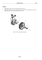
ASSEMBLY - Continued
END OF TASK
INSTALLATION
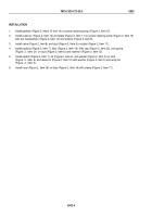
1.
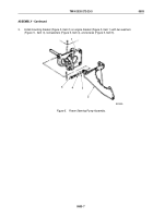
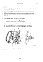
Install adjusting link (Figure 6, Item 11) on mounting bracket (Figure 6, Item 16) with washer
(Figure
6,
Item
12), screw (Figure 6, Item 13), washer (Figure 6, Item 10), and locknut (Figure 6, Item 9).
2.
Install adjusting link (Figure 6, Item 11) on engine (Figure 6, Item 19) with washer (Figure 6, Item 15) and screw
(Figure 6, Item 14).
3.
Install steering pump (Figure 6, Item 2) on mounting bracket (Figure 6, Item 16) with three lockwashers
(Figure
6,
Item
18) and screws (Figure 6, Item 17).
NOTE
•
Do not reuse hydraulic oil.
•
Remove all caps and plugs prior to installation.
4.
Install return hose (Figure 6, Item 5) on return tube (Figure 6, Item 3) with clamp (Figure 6, Item 4).
5.
Install high-pressure return hose (Figure 6, Item 6) on high-pressure fitting (Figure 6, Item 8) and tighten nut
(Figure 6, Item 7).
M5049DAA
1
2
3
14
4
15
9
7
5
11
6
12
10
13
19
8
16
17
18
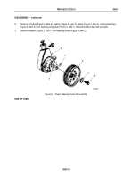
Figure 6.
Power Steering Pump Installation.
END OF TASK
TM 9-2320-272-23-3
0503
0503-8
Back to Top

