TM-9-2320-272-23-3 - Page 1321 of 1469
VAN SPARE TIRE CARRIER INSTALLATION
1.
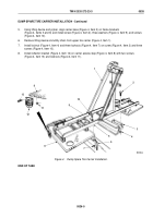
Position step brackets (Figure 6, Item 18) under carrier base (Figure 6, Item 11) with holes aligned and install
carrier access step (Figure 6, Item 19) on carrier base (Figure 6, Item 11) with four washers
(Figure 6, Item 17), screws (Figure 6, Item 16), and locknuts (Figure 6, Item 20).
2.
Attach davit chain (Figure 6, Item 15) to carrier base (Figure 6, Item 11), and using davit (Figure 6, Item 14),
position carrier base (Figure 6, Item 11) on vehicle.
3.
Using two washers (Figure 6, Item 9) and screws (Figure 6, Item 10), align carrier base (Figure 6, Item 11)
with frame rail bracket (Figure 6, Item 7), and install carrier base (Figure 6, Item 11) on muffler support
(Figure 6, Item 6) with four screws (Figure 6, Item 5) and locknuts (Figure 6, Item 12).
4.
Remove davit chain (Figure 6, Item 15) from carrier base (Figure 6, Item 11).
5.
Install two locknuts (Figure 6, Item 8) on screws (Figure 6, Item 10).
6.
Install carrier base (Figure 6, Item 11) on mufller support brace (Figure 6, Item 3) with two washers
(Figure 6, Item 2), screws (Figure 6, Item 1), washers (Figure 6, Item 2), and locknuts (Figure 6, Item 4).
TM 9-2320-272-23-3
0526
0526-8
Back to Top


